


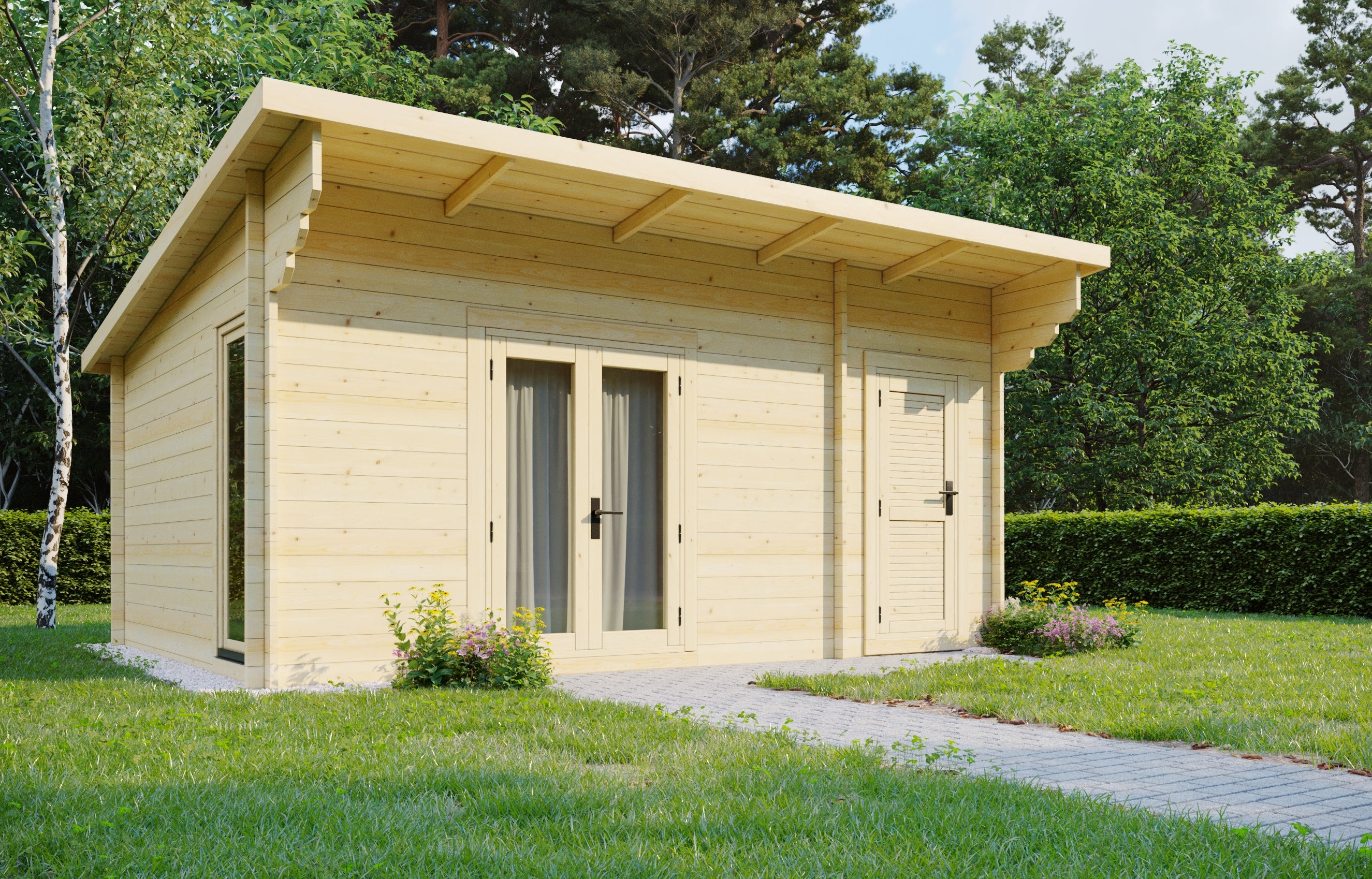
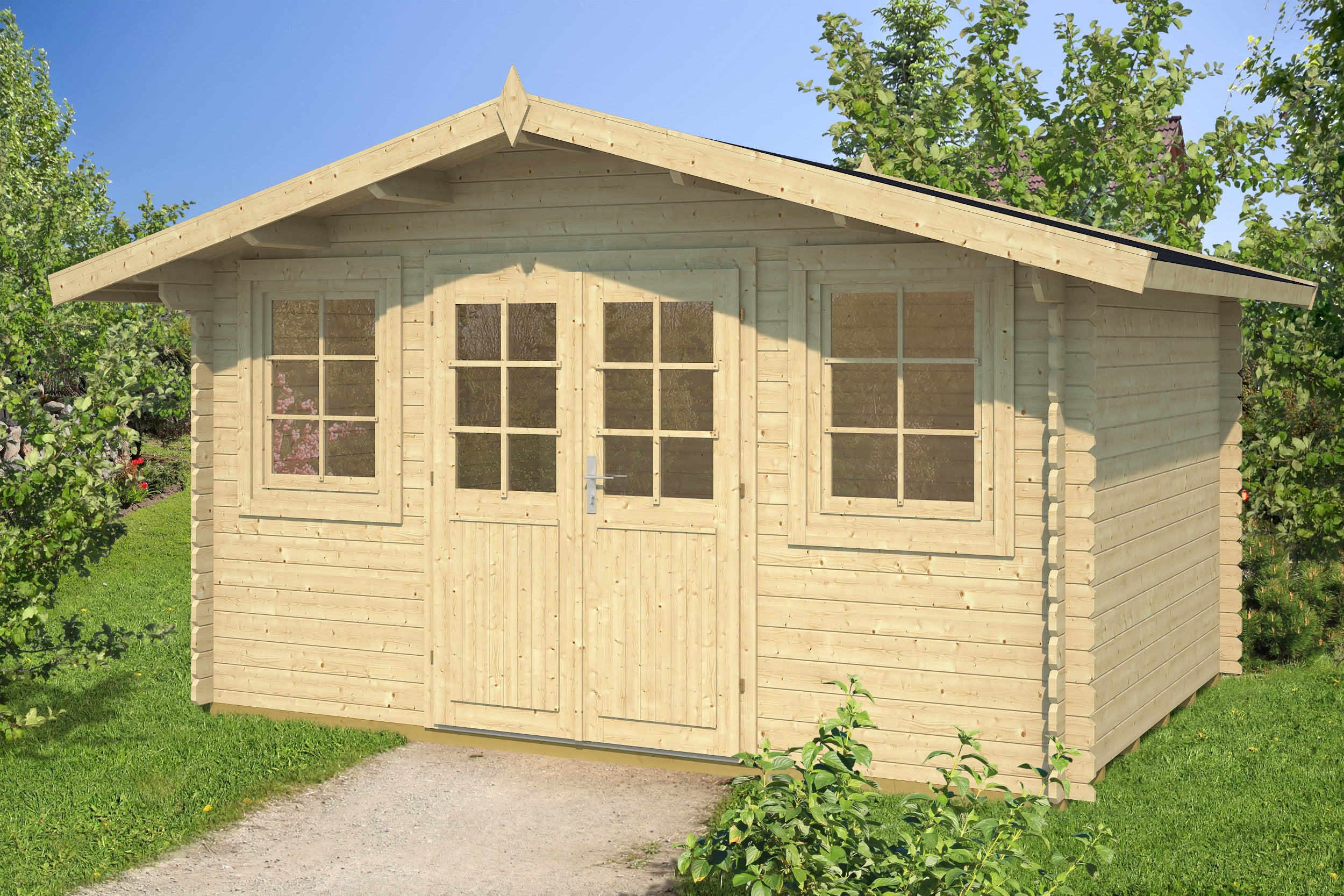
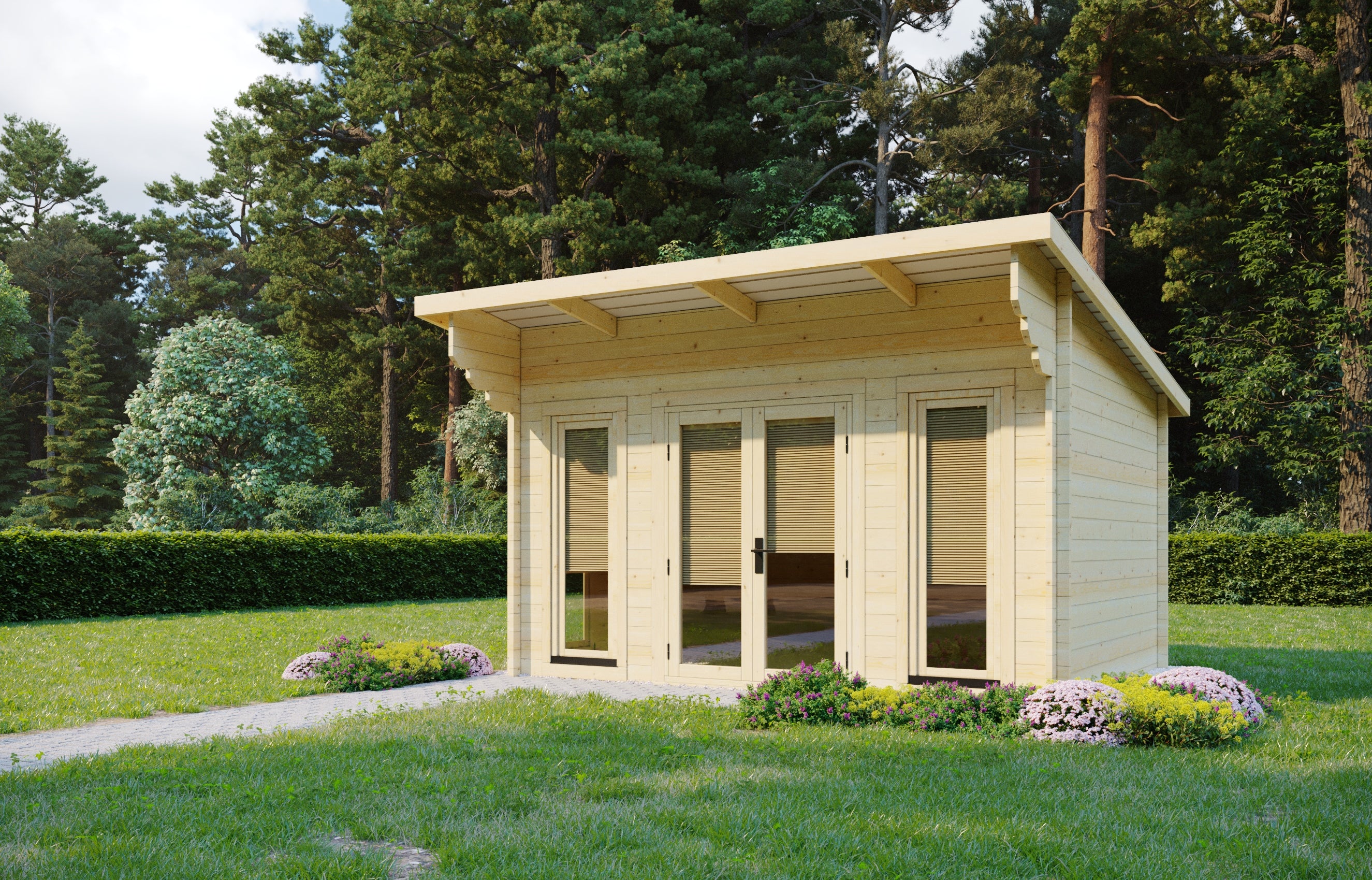


Building the ‘NICE’ Log Cabin
Building a log cabin; A Case Study By Winston Platt

Ground Preparation
Before delivery of the kit the base was prepared. A digger & driver were hired to remove the turf & level the ground as accurately as possible.
A trench was dug at the same time for an armoured electric cable to provide power to the cabin.

Level The Base
A compactor was hired to firm up the ground, & two bulk bags of 40mm down crusher run were used to build up the base where required for levelling. The compactor was again used to firm up the crusher run to provide a level base for the ‘Ecodeck’ interlocking plastic base for the cabin. Before the ‘Ecodeck’ was fitted a porous membrane was laid.
A lesson learned was that the compacted crusher run base was not levelled with sufficient accuracy. There was an error corner to corner of 32 mm, & although no requirement was given in the instructions other than ‘level,’ a target of 20 mm was thought to be a practical & acceptable level tolerance.

Cabin Base Frame Assembly
The ‘Ecodeck’ base was then fitted over a porous membrane, & the pockets filled with pea gravel.
The 32 mm error was corrected by fitting plastic shims between the ‘Ecodeck’ base & the cabin base frame, at 0.5 m centres. The result was a relatively level base.

Keep the site dry
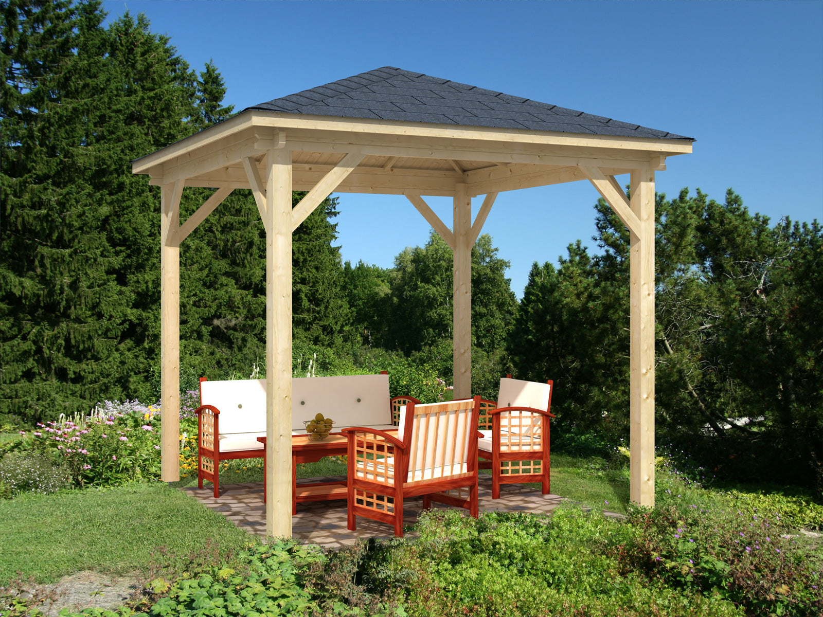
Before the cabin base frame was laid & assembled, a 6 m x 3 m gazebo was erected to help keep the site dry, as this was in early October & the weather was variable.
A selection of various thickness plastic spacers was cut. These were approx. 70 mm x 70 mm, & thickness ranged from 1.5 mm to 15 mm.
The ends of the frame timbers were treated with wood preservative as an extra precaution. The base was then assembled & levelled around the load bearing periphery using the above plastic spacers. These were finally screwed through the frame timbers using 60 x ø4.5mm stainless steel screws (not supplied) to prevent the spacers from moving. The first lower logs were positioned & fixed in position as per the plan. Expanding foam was applied to seal any gaps between the frame & the ‘Ecodeck’ grid. This would not have been necessary if the ‘Ecodeck’ base was level.
It was discovered that the 70mm long screws supplied gave a very minimal engagement length in the frame, so 100 x 6mm stainless steel screws were substituted (not supplied).
• It is suggested that longer screws are used to fix the lowest logs to the cabin base.
Some additional plastic packing pieces (1.5 – 15 mm thick, size 50mm x 70mm) were cut for the floor joist levelling.
The floor joists were levelled using the above spacers at 0.5 m centres, which were held in position by screwing 60 x 4.5 mm stainless steel screws as for the base frame.

Log Cabin Assembly
The walls were then built up to 8 to 10 logs. A rubber mallet was not effective for settling the logs, so a clout hammer with a piece of waste log was used & proved to be much better!

Installing The Windows
The 4 windows were fitted at this stage, but not the door. The walls were then built as high as possible under the gazebo. The gazebo was then dismantled, and the walls were built to full height.

Roof Purlins
The purlins were then fitted, & fixed using the screws supplied. All the roof boards were fitted including the end boards which required trimming to length.

Installing the Treadplate
At this stage the door frame was assembled with the treadplate, (which was later found to be fitted the wrong way & had to be reversed so that the LH door catch aligned with the hole in the treadplate).
The inside face boards were positioned & screwed to the door frame, & then removed and the frame assembly inserted into the full height door aperture. The inside face boards were then replaced & screwed to the frame assembly to hold it in position within the cabin wall.
At this stage the first coat of preservative was applied to the external surfaces of the cabin.

Roof Shingles
The roof shingles were then fitted as per the instructions. These were fixed directly to the roof boards, without an additional roof felt layer. A length of small section timber was temporarily screwed to the roof boards to act as a guide for the top edge of the lowest row of shingles. A heat gun was used to ease the bending of the ridge shingles. Clout nails were easily obtained.
The gable end ‘L’ sections were glued & screwed together as sub-assemblies. These were then treated with two coats of wood preservative & screwed to the ends of the purlins.
A roof sealant bead was fitted in the ‘V’ at the apex of the roof trims to prevent rainwater from getting behind the trim, & the decorative ‘diamonds’ were fitted.
A second coat of wood preservative was applied at this time.

Cabin Floor; Insulation Plan & Power Supply
It was decided to fit 50 mm ‘Recticel’ or ‘Kingspan’ rigid foam insulation boards in three areas –
• Floor
• Roof
• Behind IKEA ‘Billy’ bookcases to be fitted later.
It was calculated that these measures would reduce the heat requirement for 21°C inside temperature at -1°C ambient, from approx. 4kW to 2kW.
To fit the insulation boards between the joists, pea gravel was added to leave a 50 mm gap for the insulation. This was achieved by making a 50 mm depth gauge as shown in the photo. Thus the top face of the insulation boards was flush with the top of the joists.


Log Cabin Insulation
The underfloor insulation boards were fitted & channels cut to lay the 2.5 mm² cable for floor mounted sockets. The cables were laid & the floorboards & floor mounted sockets fitted.

Lighting Circuit & Insulated Ceiling
A 1.5 mm² cable for the lighting circuit was fitted into the corners & through the central purlin so that the cable was hidden wherever possible. The supply for the light circuit came up in the rear RH corner of the cabin, & most of this would be covered by the ‘Billy’ bookcases installed later. A plywood ‘conduit’ was constructed for this corner between the bookcase top & the ceiling to hide the cable as much as possible.
The insulation boards were cut to fit between the purlins & directly under the roof boards. Where the boards met the vertical walls, & the centre purlin, the edges were cut at 16° to ensure as close a fit as possible.

The boards were then fixed to the roof boards with a contact adhesive, and ceiling boards cut from 5.5 mm plywood were screwed through the insulation boards into the roof boards using 70 x ø5 screws. The holes in the plywood were pre-drilled & countersunk so that the screw heads would not protrude below the ceiling level. The ceiling boards were fixed on all the edges, with some fixings in the centre of the boards. Although the plywood was buckled on delivery, the screws pulled it against the insulation boards & resulted in a relatively flat surface. The screw heads were filled with decorators caulk to hide the screws as much as possible. Fitting the larger ceiling boards required two people.

Robus ‘Acorn’ track lights were then screwed to the central purlin after cutting them to the correct length.
The ceiling was then finished with emulsion paint, & the interior walls were treated with wood preservative.

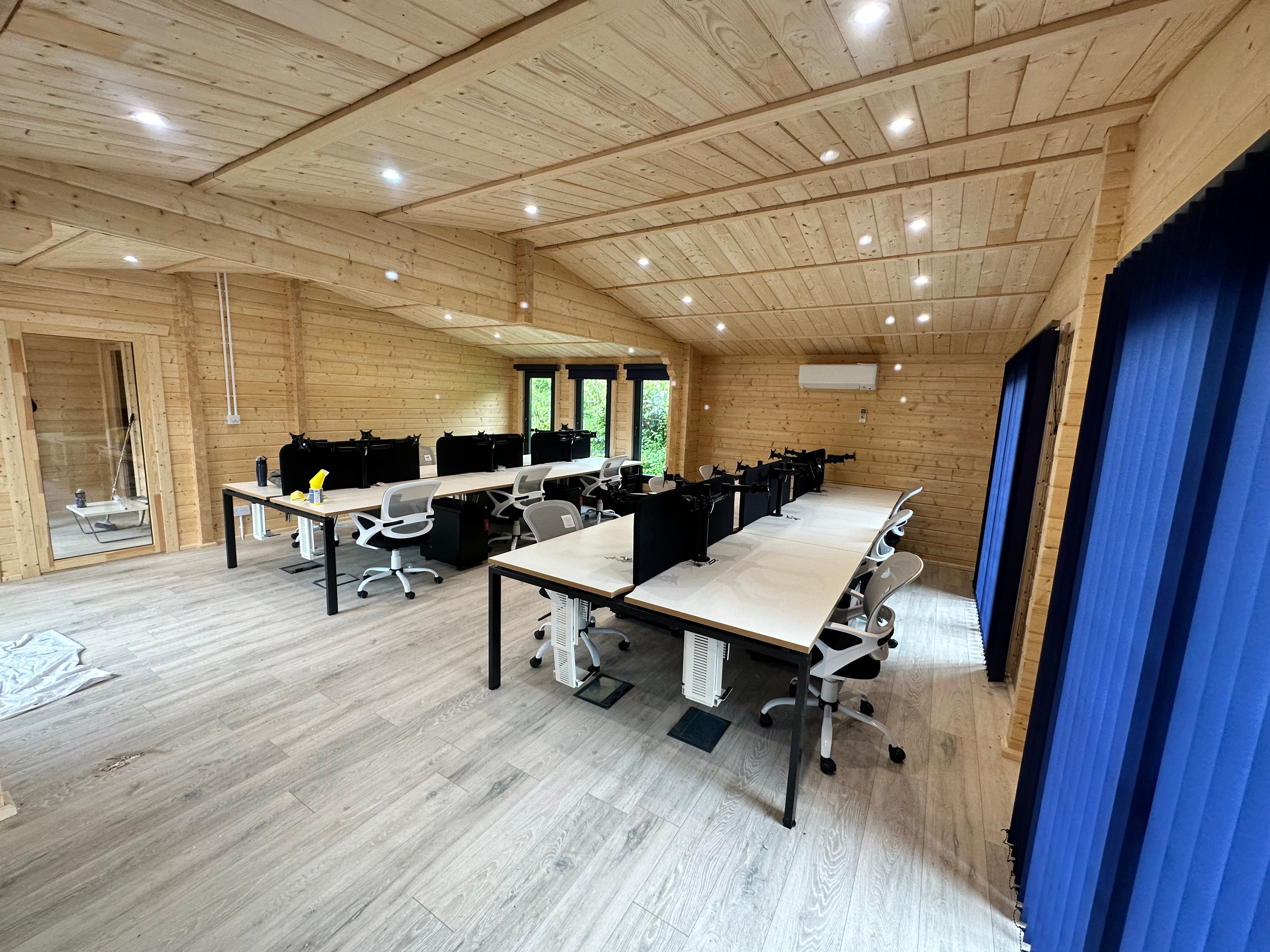
Finishing the Home Office
Several ‘Billy’ bookcases were fitted, and insulation was fixed to all the areas with adhesive, back & ends, which abutted the cabin walls.

As the cabin walls would shrink when drying out; special brackets were made to fix the tops of the cabinets to the cabin walls. These were made from 44 mm fence panel clips drilled ø6 mm on the legs; 50 mm x ø6 bolts & nuts; and a bracket made from aluminium strip bent in a ‘Z’ shape drilled on one leg for screws to fix to the cabinet top; and on the other leg drilled to a clearance fit for the ø6 mm bolt. The aluminium bracket was screwed to the top of the cabinets. The bolt passed through the top leg of the fence bracket which was screwed to the cabin wall, through the aluminium bracket, & finally through the bottom leg of the fence bracket & nutted up.
This allowed the wall, with the fence bracket, bolt & nut, to move down through the hole in the aluminium bracket, without crushing the cabinet.
Finally, panels made from 5.5 mm plywood were cut to hide the edges of any visible insulation.

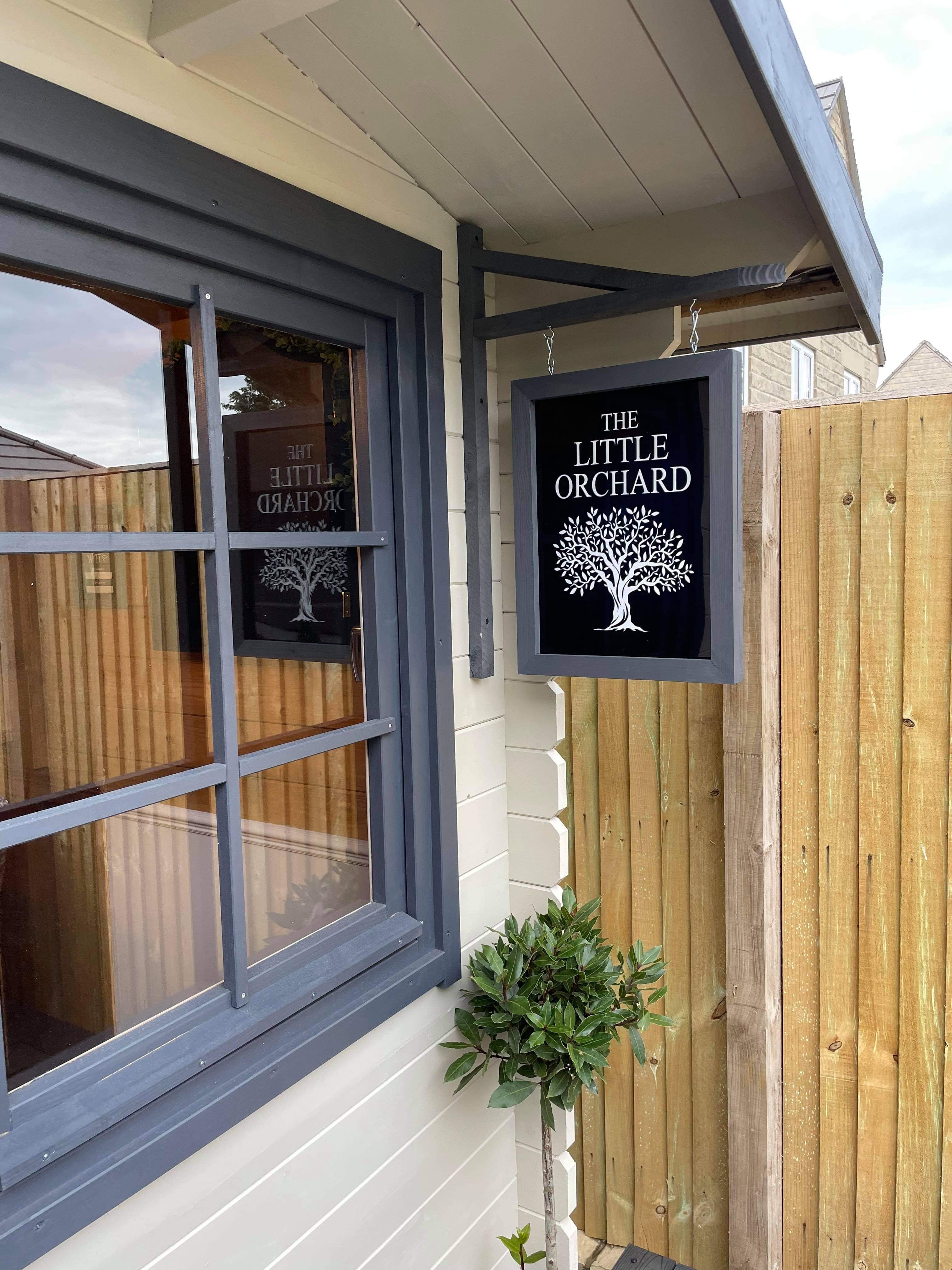
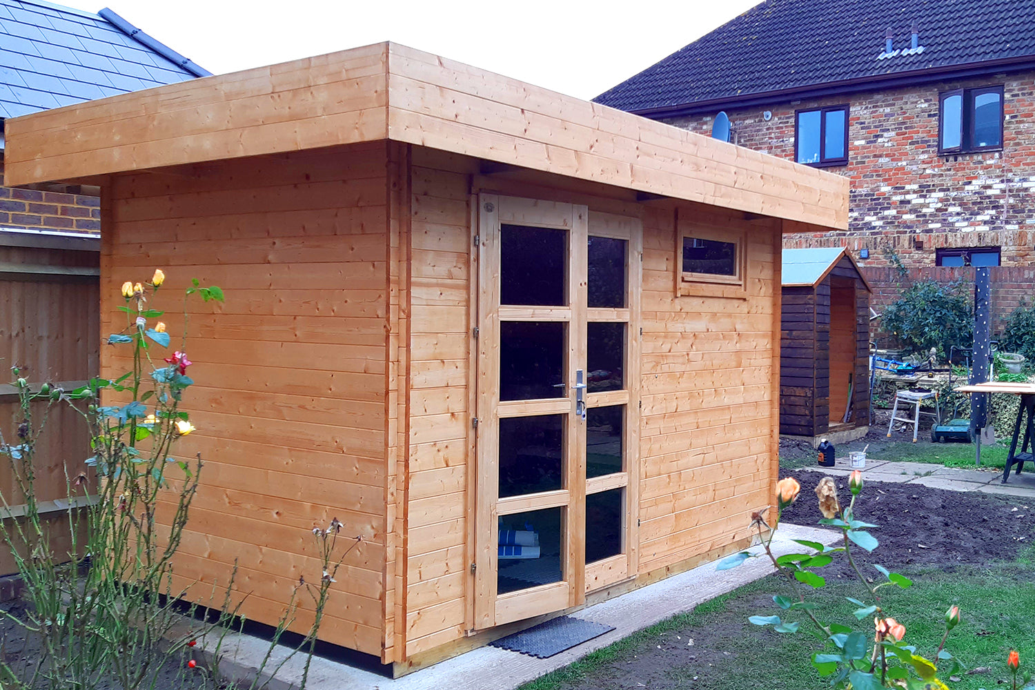
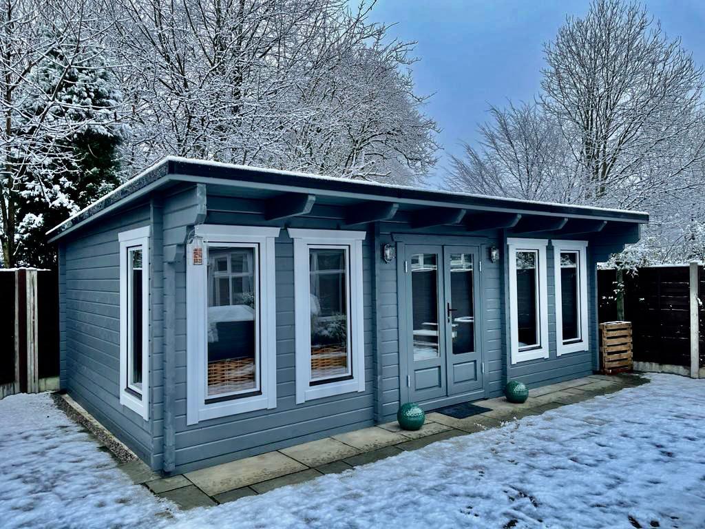
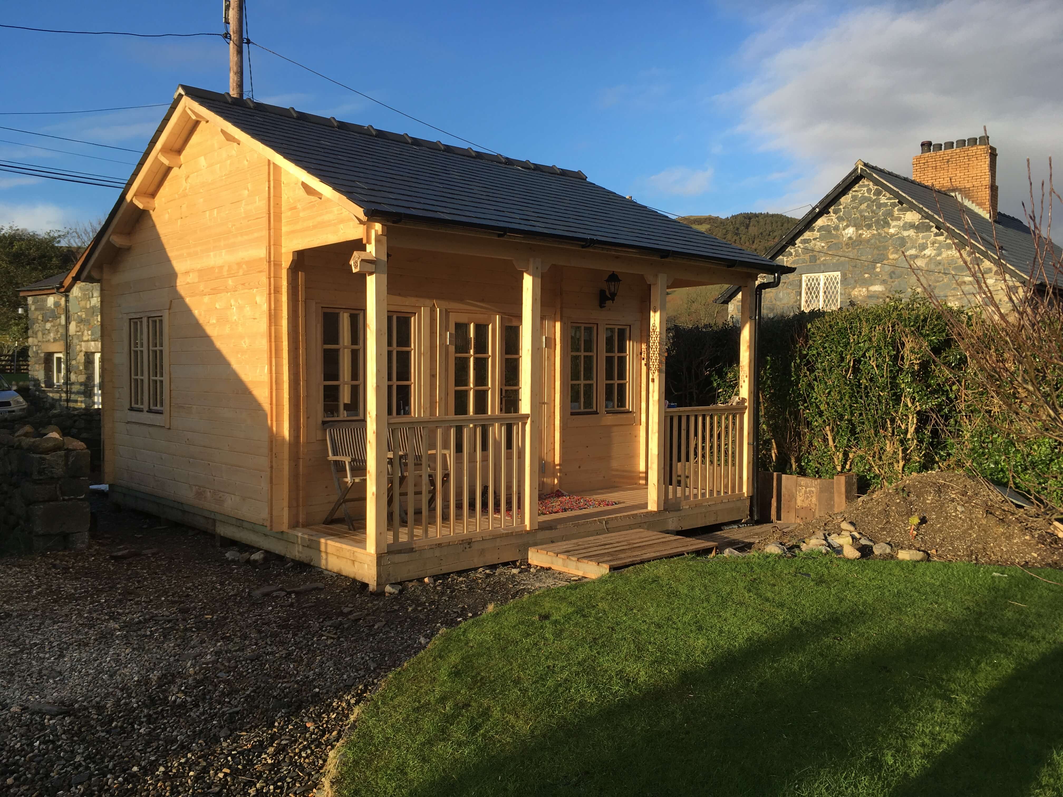
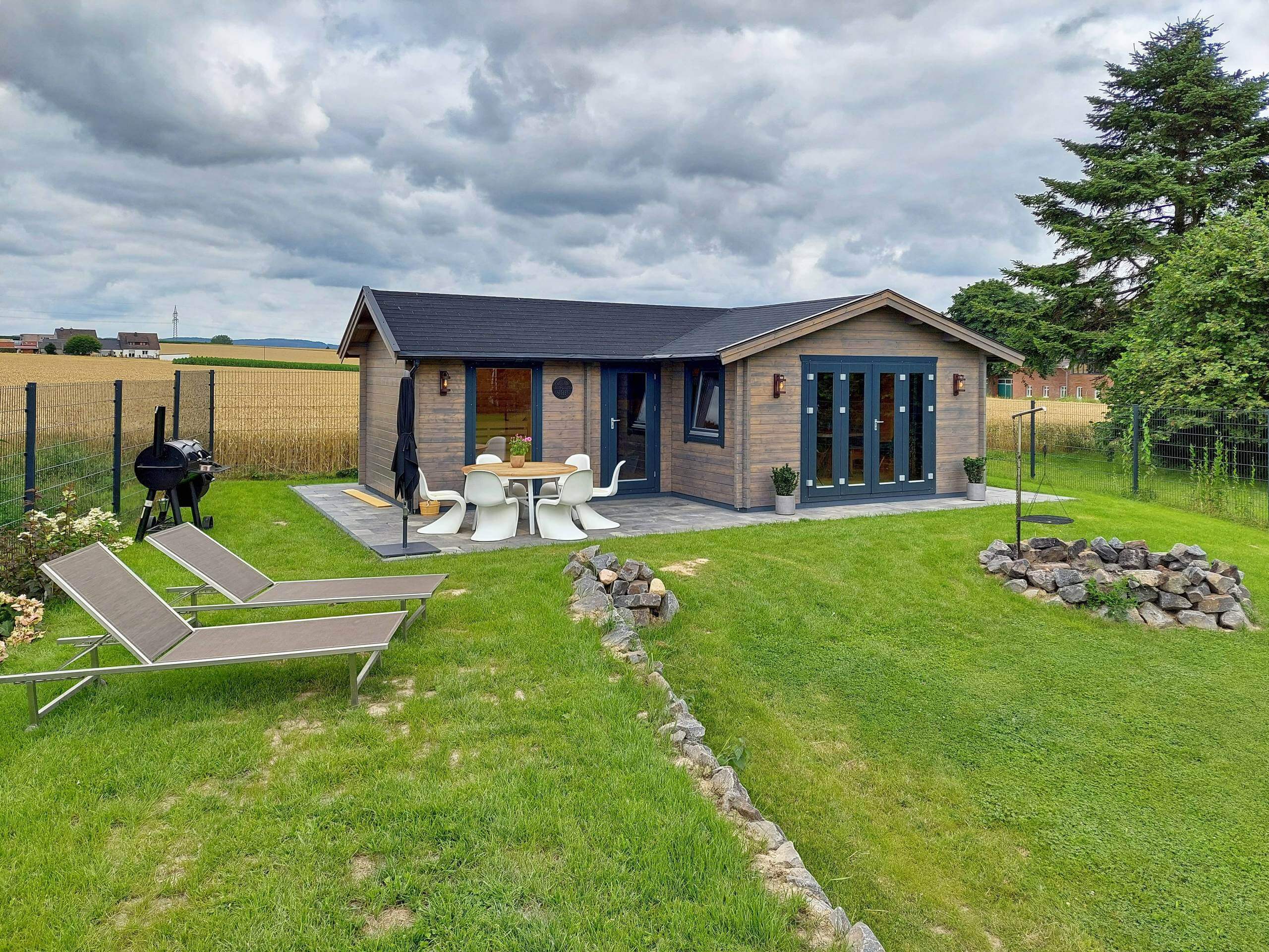
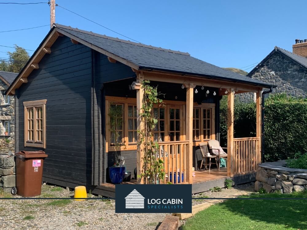
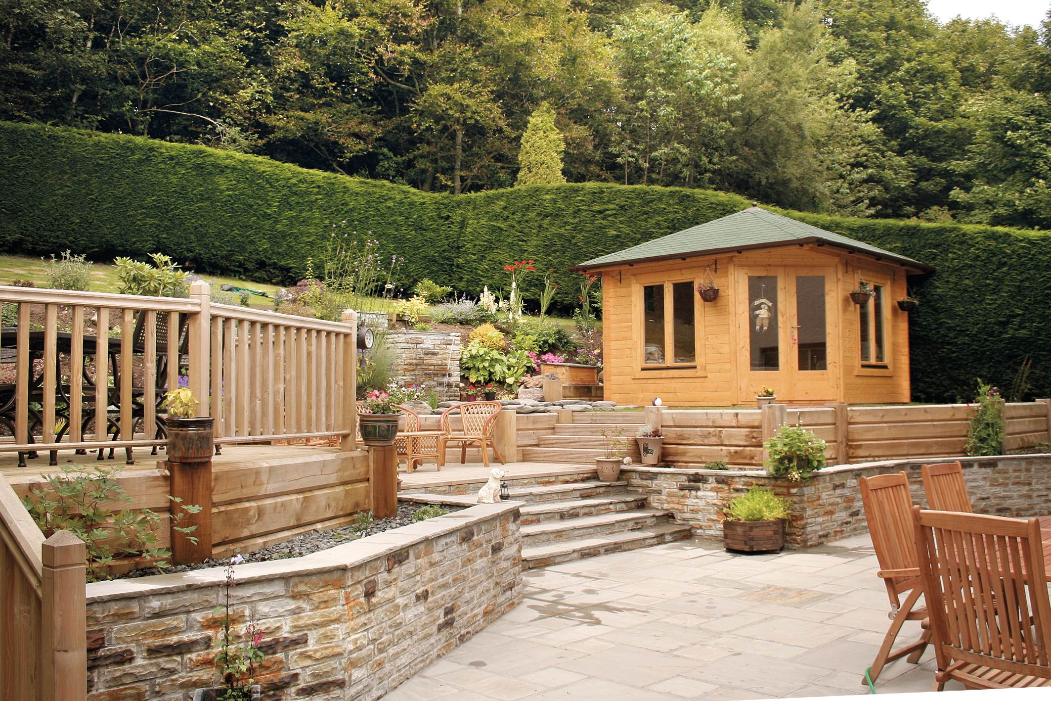
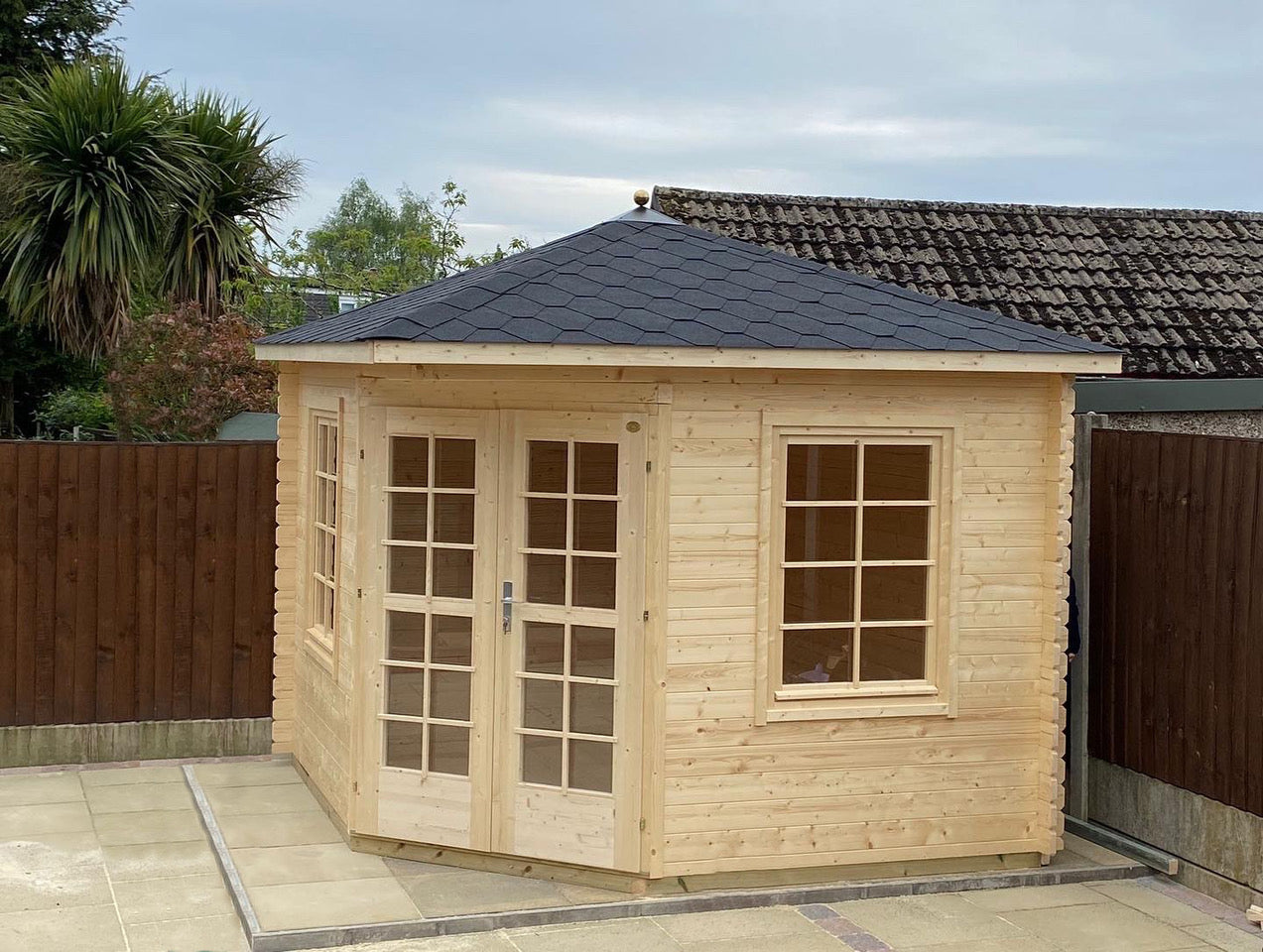
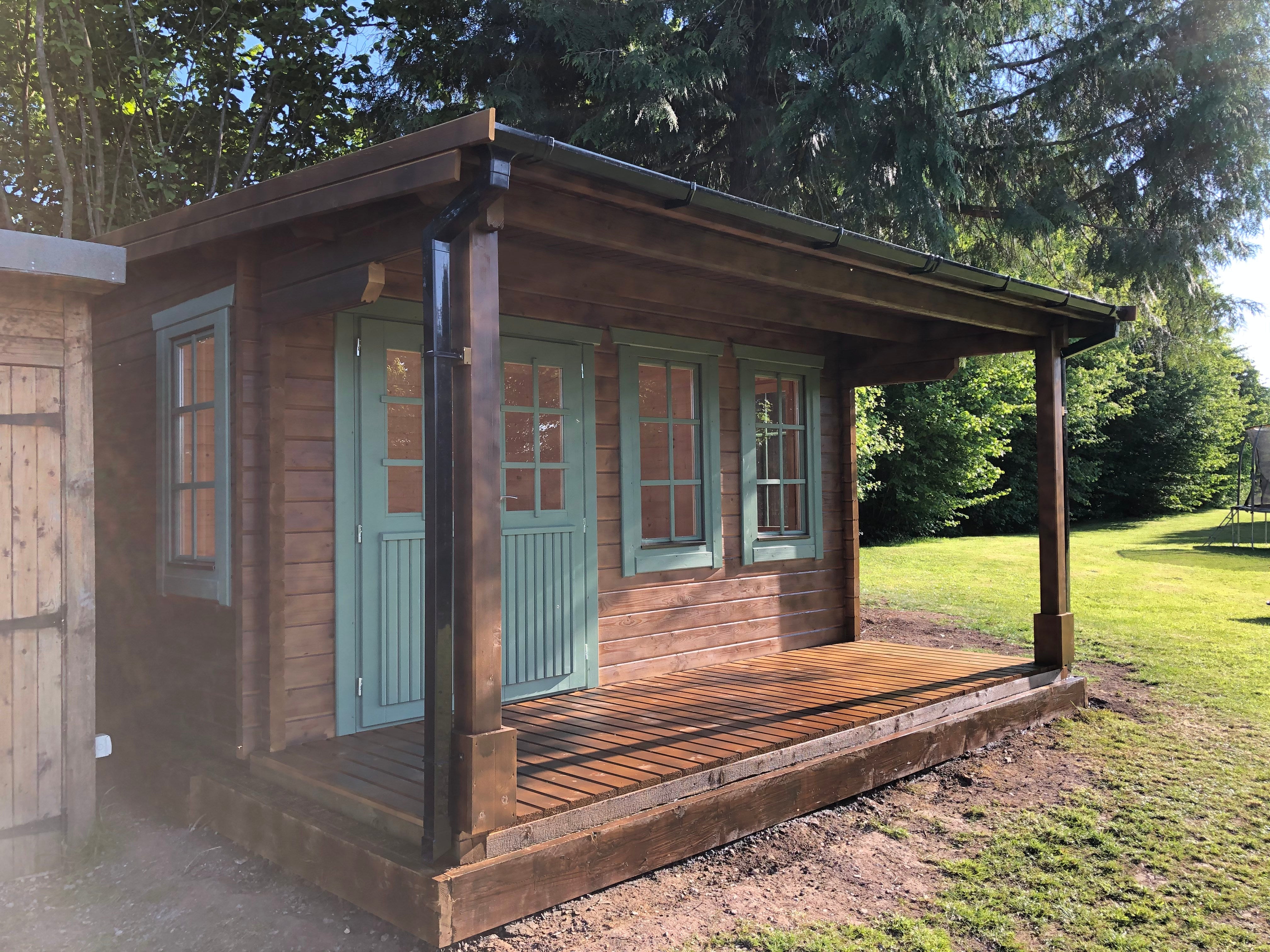
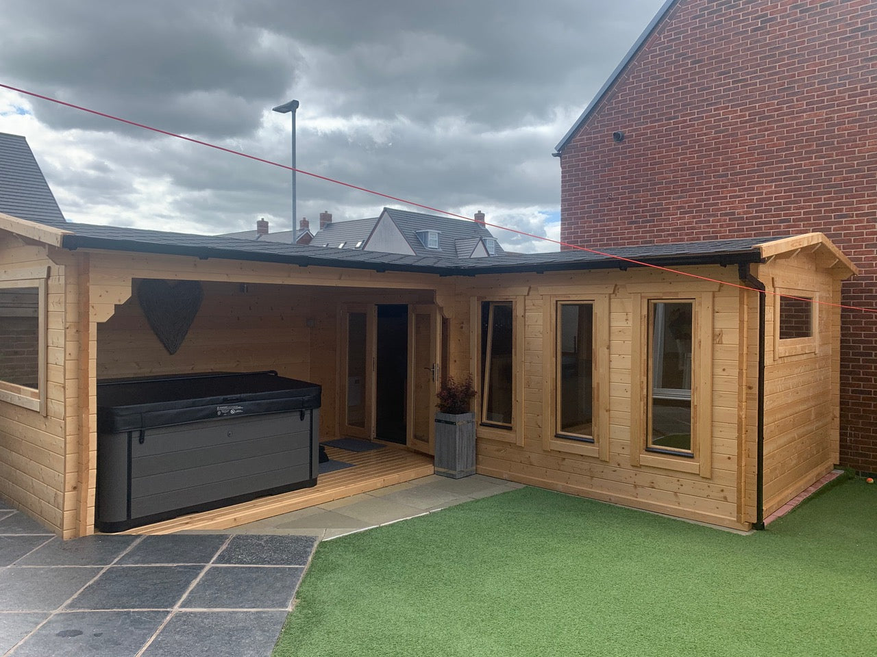
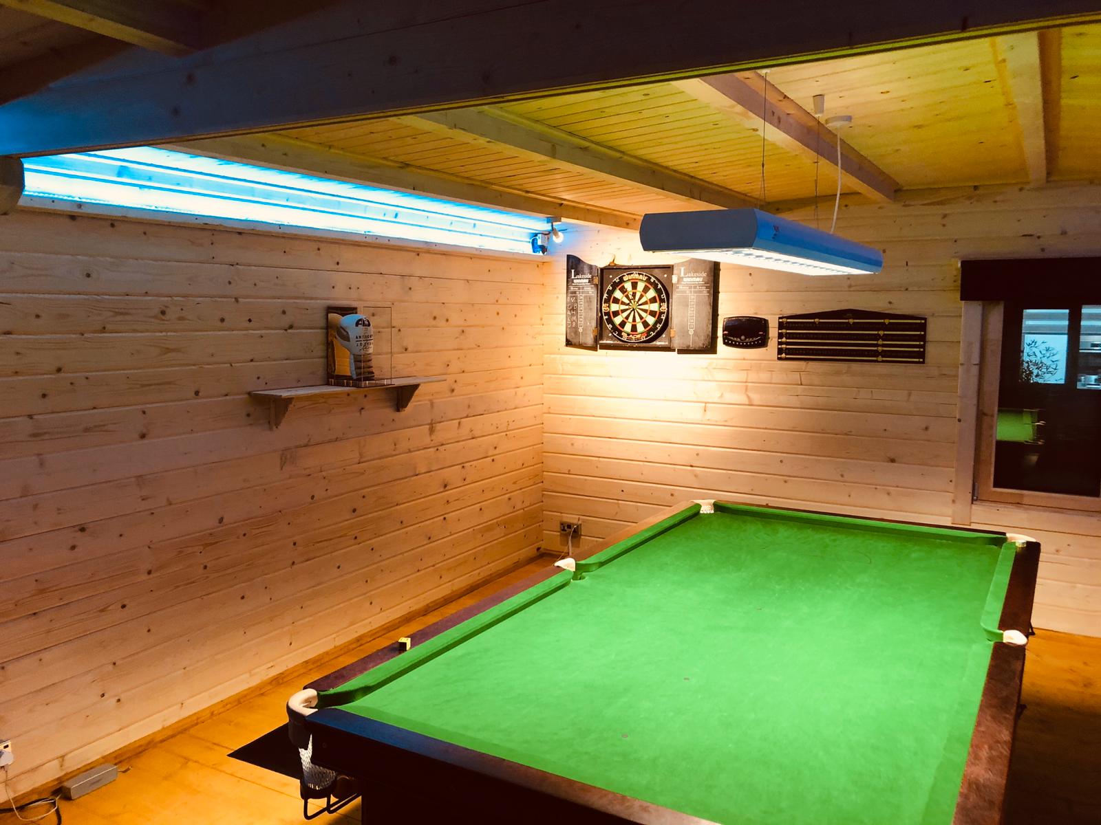
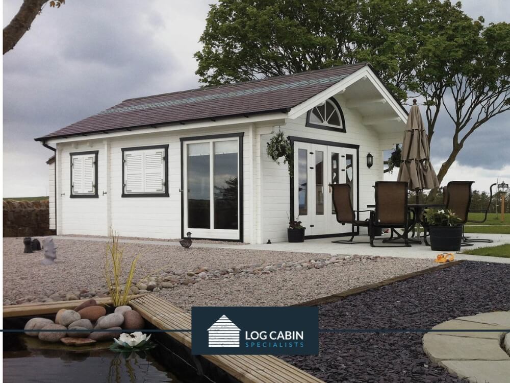
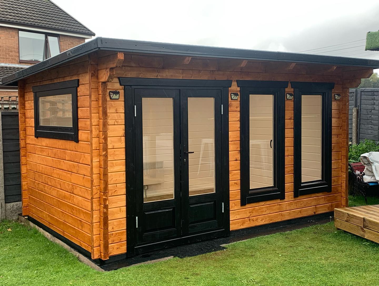
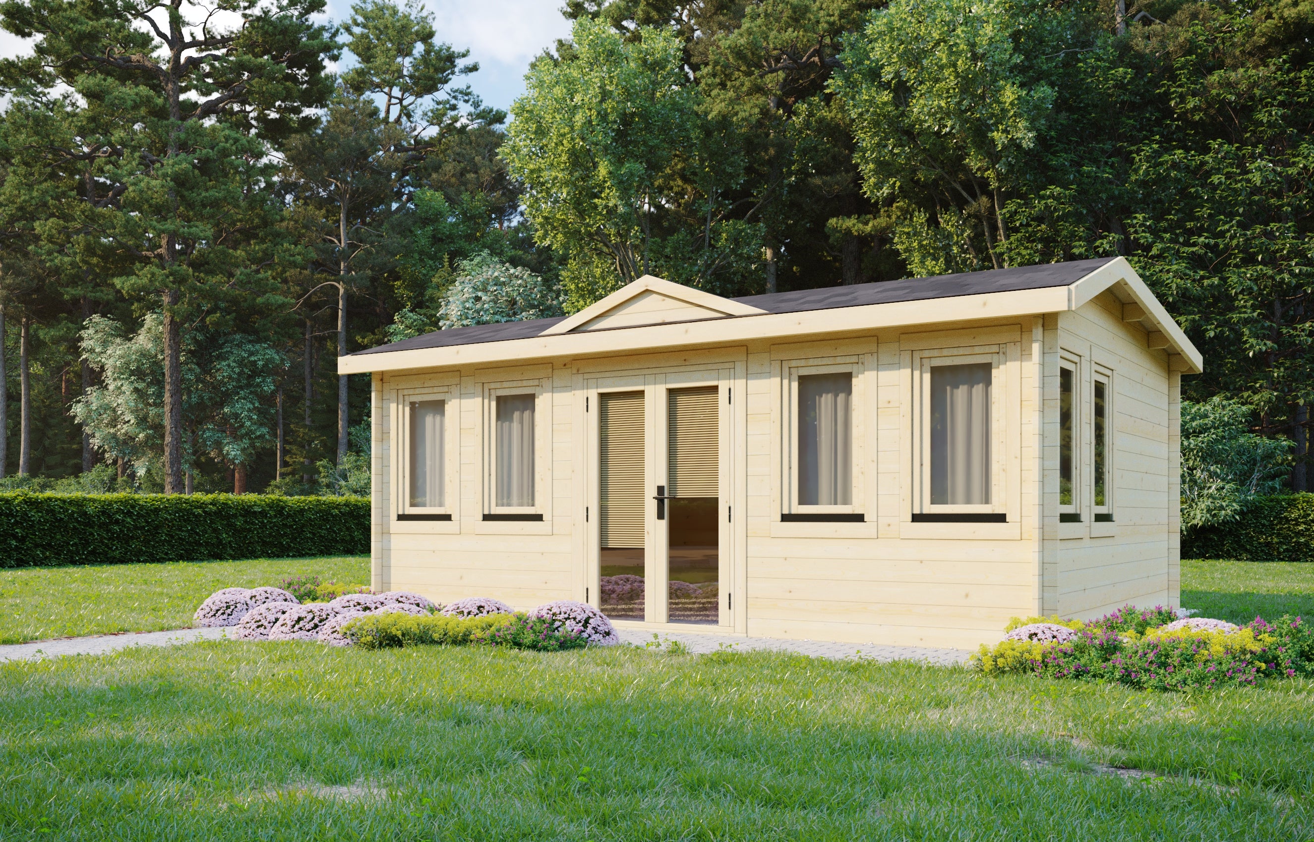
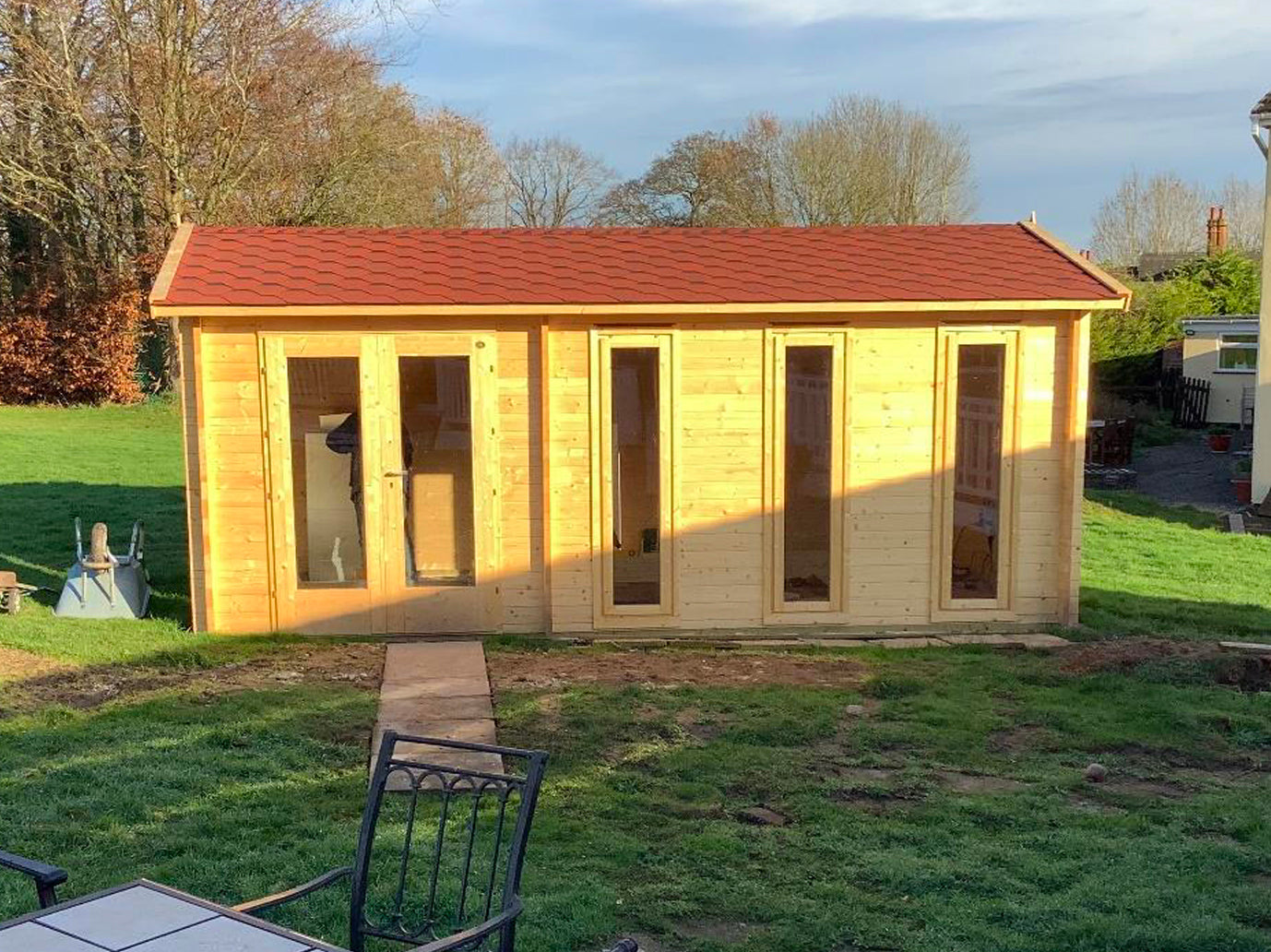
Finished Log Cabin
Here are photos of the finished product, which is used as a home office & summerhouse. Carpet tiles were used on the floor.

Gutters
A recent addition has been the fitment of a gutter, downpipe & rainwater butt. ‘FloPlast’ 76 mm products were chosen in brown, which seems to blend in well with the walls & roof shingles. Timber wedges had to be made to fix to the angled facia boards to provide a vertical surface for the gutter brackets.